‹

›
‹
›
10kV S13-M.RL/S11-M.RL Series Hermetically Sealed Three-phase

OEM CAPABILITY
BRAND REPUTATION
PRODUCTION ADVANTAGE
GLOBAL AFTER-SALES SERVICE
- PRODUCT PARAMETERS -
Product Description
The S13-M.RL/S11-M.RL series hermetically sealed three-phase tridimensional toroidal-core transformer produced by our company is different from traditional planar toroidal-core transformers. Its core is composed of three identical single frames combined in a triangular structure, with each frame continuously wound from high-quality cold-rolled silicon steel strips. The strip width is cut straight or curved by a CNC machine. High-voltage and low-voltage windings are wound directly on the core columns using a special winding machine, resulting in a solid and compact overall structure.
Product Features
- The three-phase three-limb symmetrical structure provides the most balanced three-phase magnetic circuit, with completely symmetrical magnetic circuits of equal and shortest length. The three-phase no-load current is completely balanced, eliminating third harmonics and ensuring the quality of the power supply waveform. Due to the excellent core material and winding process, not only the no-load loss is small, but also the no-load current and noise are significantly reduced.
- The transformer body is in the shape of a three-dimensional triangular prism, with tension rods installed in the center and periphery. It is integrated with the upper and lower iron yokes and laminated wood, effectively resisting axial and radial mechanical stress during sudden short circuits.
- The transformer features a compact structure, small footprint, saving installation space, and convenient installation and maintenance.
Technical Parameters
Notes:
- For transformers with a rated capacity of 500kVA and below, the load loss values above the diagonal line apply to Dyn11/Yzn11 connection groups, and those below the diagonal line apply to Yyn0 connection groups.
- According to customer needs, we can provide other high-voltage tapping ranges of ±2×2.5%.
- According to customer needs, we can provide transformers with a low voltage of 0.69kV.
- If the user has other needs, they can choose other loss values.
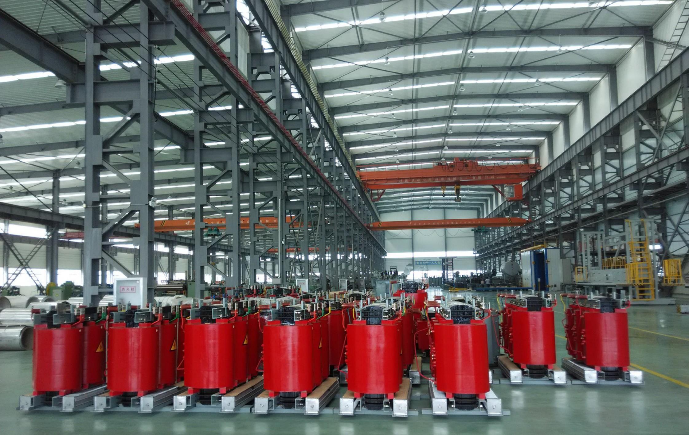
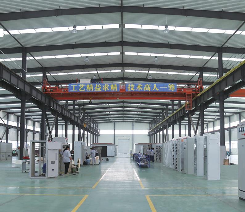
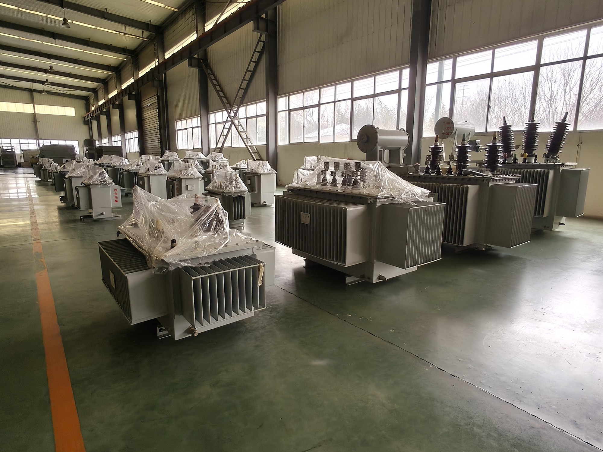
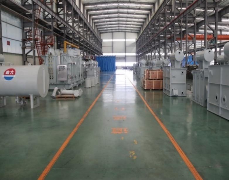
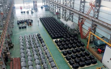
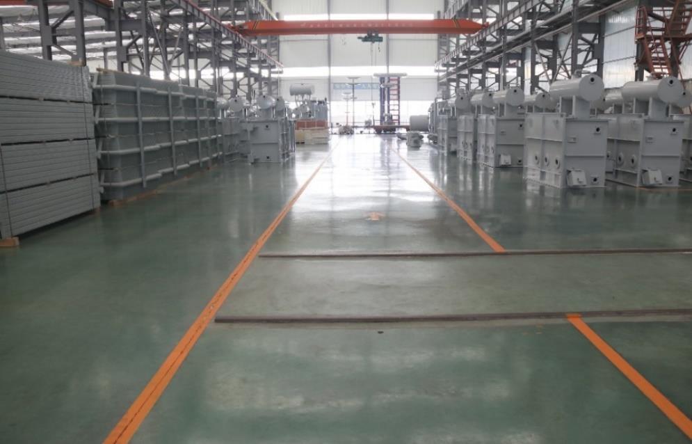
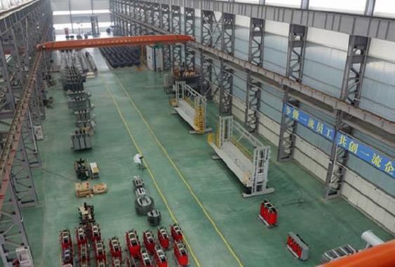
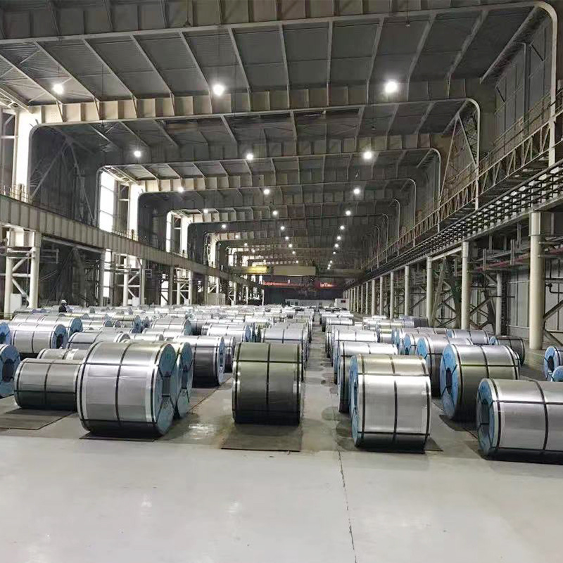
- Factory Display -
- Inquire Now -
We have established long-term and stable strategic partnerships with high-quality enterprises in various fields, and have won the widespread recognition and trust of our partners.


- Related Product -
 Solar Photovoltaic PanelsLearn More
 InverterLearn More
 Zinc IngotLearn More
 Zinc IngotLearn More
 Zinc IngotLearn More
 Insulation PaperLearn More
 HV&IV SwitchgearLearn More
10 Series Non-Encapsulated Dry-type Transformer") 10kV SG(B)10 Series Non-Encapsulated Dry-type TransformerLearn More
10kV SG(B)10 Series Non-Encapsulated Dry-type TransformerLearn More10 Series Epoxy Resin Cast Dry-type Transformer") 10kV SC(B)10 Series Epoxy Resin Cast Dry-type TransformerLearn More
10kV SC(B)10 Series Epoxy Resin Cast Dry-type TransformerLearn More 10kV D11 Single-phase Distribution TransformerLearn More
 10kV S11-M.ZT/S13-M.ZT Series On-load Capacity Regulating Power TransformerLearn More
 10kV S13-M.RL/S11-M.RL Series Hermetically Sealed Three-phaseLearn More
 35kV S11, SZ11 Series Oil-immersed Power TransformerLearn More
 110kV Power TransformerLearn More
 220kV Oil-immersed Power TransformerLearn More
 SCBH15-M Series Amorphous Alloy Dry-type TransformerLearn More
H15-M Series Amorphous Alloy Oil-immersed Transformer Product Description") S(B)H15-M Series Amorphous Alloy Oil-immersed Transformer Product DescriptionLearn More
S(B)H15-M Series Amorphous Alloy Oil-immersed Transformer Product DescriptionLearn More Special Transformer — High Overload TransformerLearn More
 Special Transformer — Mining General Type Power TransformerLearn More
 Rectifier TransformerLearn More
 HXGN-12 AC Metal-Enclosed SwitchgearLearn More
 KYN28A-12 Armored Central AC Metal-Enclosed SwitchgearLearn More
 Armored Metal-Enclosed Switchgear") KYN61-40.5(Z) Armored Metal-Enclosed SwitchgearLearn More
KYN61-40.5(Z) Armored Metal-Enclosed SwitchgearLearn More Box Type Fixed AC Metal-Enclosed Switchgear") XGN2-12(Z) Box Type Fixed AC Metal-Enclosed SwitchgearLearn More
XGN2-12(Z) Box Type Fixed AC Metal-Enclosed SwitchgearLearn More / XGN15-12(F·R) Box Type Fixed AC Metal-Enclosed Switchgear") XGN15-12(F) / XGN15-12(F·R) Box Type Fixed AC Metal-Enclosed SwitchgearLearn More
XGN15-12(F) / XGN15-12(F·R) Box Type Fixed AC Metal-Enclosed SwitchgearLearn More XL-21 Power Distribution CabinetLearn More
 GCK Type Low-voltage Withdrawable Complete SwitchgearLearn More
 GCS Type Low-voltage Withdrawable Complete SwitchgearLearn More
 GGD Low-voltage Fixed Complete SwitchgearLearn More
 MNS Type Low-voltage Withdrawable Complete SwitchgearLearn More
 Metal-cased prefabricated substationLearn More
 ZGS11-10 American-style prefabricated substationLearn More
") YB-12 Prefabricated Substation (European-style box-type substation)Learn More
YB-12 Prefabricated Substation (European-style box-type substation)Learn More High-voltage cable branch boxLearn More
 10-20KV Power Transformer Corrugated Oil TankLearn More
 Rectangle Wire") Enameled Copper (Aluminum) Rectangle WireLearn More
Enameled Copper (Aluminum) Rectangle WireLearn More Oriented SiliconLearn More


10 Series Non-Encapsulated Dry-type Transformer")
10 Series Epoxy Resin Cast Dry-type Transformer")


H15-M Series Amorphous Alloy Oil-immersed Transformer Product Description")


 Armored Metal-Enclosed Switchgear")
 Box Type Fixed AC Metal-Enclosed Switchgear")
 / XGN15-12(F·R) Box Type Fixed AC Metal-Enclosed Switchgear")


")


 Rectangle Wire")


Xinda Electric Power (Shandong) Co., Ltd.
If you are interested in our products and want to know more details,please leave a message here,we will reply you as soon as we can.